
Descrizione
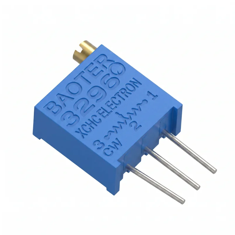
The 3296W trimmer is a multiturn variable resistor designed for fine adjustment of electrical parameters in electronic circuits. The vertical adjustment axis and pin pitch for printed circuit boards (PCBs) allow for use in calibration, setting reference values, and device servicing.
Technical specifications
Type: 3296W trimmer
Design: Multiturn variable resistor
Characteristic: Linear
Resistance tolerance: ±10%
Power rating: 0.5 W
Number of turns: 25
Adjustment angle: 9000° ±20°
Axis: Vertical
Dimensions: 9.53 × 4.83 × 10.03 mm
Pin pitch: 2.54 mm
Mounting: PCB through-hole
Features and properties
Allows fine resistance adjustment using a multiturn mechanism.
The linear resistance curve is suitable for adjustments in both analog and control circuits.
The vertical axis allows access to the adjustment screw from the top of the board.
The three pins correspond to use as a variable resistor or voltage divider, depending on the circuit wiring.
The availability of multiple resistance values allows choosing a variant according to the required adjustment range.
Ideal for
Calibration of electronic circuits.
Setting reference voltage or operating point.
Service modifications and laboratory prototypes.
Mounting on printed circuit boards in low-power applications.
Development, measuring, and control circuits requiring fine resistance adjustment.
Package contents
1x 3296W trimmer in the selected resistance variant.
Why choose this product
The multiturn design allows for more precise adjustment than single-turn trimmers.
The specified power rating of 0.5 W is suitable for low-power adjustment applications.
The 2.54 mm pin pitch corresponds to the standard grid used on printed circuit boards.
Variants with different resistance values cover a wide range of common adjustment needs.
Vertical adjustment is suitable for boards where access to the trimmer is from above.
Installation and operation instructions
Before mounting, check the selected resistance value and pin wiring in the specific circuit.
Do not overheat the pins and component body during soldering.
Perform adjustments using a suitable screwdriver without excessive mechanical force.
Do not exceed the specified power rating of the component.
Safety warnings
The component is intended for use in electronic circuits and requires correct wiring according to the device design.
Incorrect wiring or exceeding the power rating can lead to overheating, component damage, or circuit failure.
Installation in devices connected to hazardous voltage may only be performed by a person with appropriate electrical qualifications.
Before handling the populated board, disconnect the power supply and discharge any energy storage elements in the circuit.
Recensioni
Ancora non ci sono recensioni.